Tuesday 8 January 2008

Monday 3 December 2007

RF Assignments

Assignment 8

Antenna Types

  • The dipole is the fundamental unit of antenna design. The impedance of a dipole at its center frequency is about 70 ohms. Impedance is the ratio of voltage to Amperage combined with the "springyness" of a circuit. in the mechanical sense it is like having a number for torque plus RPM combined with a measure for how much the metal twists in a vehicle power train. In the electrical world an impedance transformer (or any transformer) is exactly like a gear box in the mechanical world. By convention transmitters and commercial receivers are designed to operate with 50 ohm systems,


  • while consumer receivers are designed to operate with 75 ohm systems

  • Folded dipoles are dipoles with an extra wire. The extra wire changes the dipole impedance to about 300 ohms if the extra wire and dipole wire is the same size.


  • Twin Lead Antennas are a form of folded dipole. This is a small antenna, but at a small price, so you actually get what you pay for. Not much in either case. This guy has the right ideas about how to make your own twin lead antenna.


  • Rabbit Ears.Bunnie ears are still dipoles, and small, and slightly more expensive than twin leads, though they have the advantage that you can move them around the room or outdoors in hopes of finding a better spot to get a signal. Read how I used rabbit ears on this rabbit ear link.


  • This dish clip on antenna is advertised a lot recently. Now, you should recognize this as a twisted folded dipole. Don't expect a lot of this form of dipole. It is, possibly, not better than rabbit ears, in that you cannot move it for best reception. It is outdoors, away from your TV, so maybe it could be better than an indoor antenna, if you are lucky. You will note the similarity to the twin lead type dipole, except you can't move this baby for best signal, or adjust for wavelength. If your reception is less that ideal, don't blame me! Uhg.


  • Turnstile. This is simple. The dipole has a dead spot, so set up one crosswise to the other, feed both dipoles connecting from one to the other with 1/4 wave length delay line, and you can get an omnidirectional antenna. Great if all stations, being in differing directions have perfect signals at your location. This antenna is sold as an FM Band antenna, with dipoles, usually in the "folded" form cut for the FM band. It is OK for FM, if you never have multipath (ghosting) or interference problems. Got it? Omni is almost always a bad idea, especially for TV! How many times do I have to say that? So, you might have to look elsewhere for omni TV band antennas information. Gee, you may as well use a lamp cord for an antenna. OK?. If you are going to use more antenna than lampcord, use a directional antenna, please. Why pay for something that picks up garbage you don't want as well as the fragile signal you do want? (Oh, ya, this is the basic idea behind the gigantic Batwing antennas often used to transmit TV. This antenna is great for broadcasting in all directions. It is easy to make from tubing, so it makes a good Ham antenna. As with any antenna, you can scale it it for your particular wavelength.


  • Other Omni. This antenna, sold for FM radio, is a bent folded dipole. It is advertised a an Omni, but only approximates omnidirectional reception.


  • Yagi. The Yagi antenna is narrow band, designed to work on only one channel or FM. It has the best gain for its size, and a correspondingly narrow main lobe (beam). If you need the highest gain, or to discriminate against an interfering signal 20-40 degrees azimuth off the desired signal, use a Yagi.


  • Log Periodic Logs have designed in broad bandwidth. The boom length being shared over a band of frequencies means lower gain than a Yagi, and a fatter main lobe, but far better rejection of signals off the side and rear. Logs are infrequently used except in professional settings. Usually they are expensive, large, heavy and rugged. If you have a lot of money to spend and want something that will last a very long while, check out Log periodics. These images take you to manufacturer sites.


  • Typical TV-FM VHF Only Home Antenna. If you want to get VHF channels, this is probably the type of antenna for you. If you need FM band capability, you have to look for that as well, but be careful. FM stations can easily overpower your TV. See more on that in the interference section. If an antenna is supposed to work on a range of frequencies from 50 to over 200 MHz, and still not cost much, then compromise is in order. In real life, most consumer antennas are not pure


  • Yagi, or log-periodic, but instead are a jumble of rods designed to get the most from the limited boom space over a wide range of channel


  • Typical UHF Only Home Antenna. Here, in South Central Alaska, there is no place where you should use a UHF only antenna. But if where you live you have no VHF choices, or if you want to use one antenna for VHF and another for UHF, (which I don't think is a good idea for home use, but might be right for professional installations) here are views of UHF only home antennas. Years ago, the FCC studied UHF antennas, and concluded the panel style was best at lowest cost, with the corner reflector being second best. Panels are the only all band transmitting antenna used in Europe, so it must be pretty good with tens of thousands transmitting multiple channels. I have had luck with the yagi-corner reflector style and parabolic style, except on the lowest channels. On the highest channels, the parabolic may be

  • Atypical Low Channel UHF. In the United States UHF TV channels 14-21 (470-518 MHz) are used for land mobile two way radio, making rugged, effective and inexpensive Yagi antennas commonly available in that band. You probably will need to drill holes in the boom to mount the antenna horizontally polarized. The image is my installation used to receive channel 14 for microwave relay to Kenai. The location is subject to windspeeds above 200 km/h. I used the Maxrad MYA-4903(N). The 50 ohm antenna uses an N connector. Mismatching is not critical in a broad band system like TV so long as the antenna is only used to receive a signal and the mismatch is at the antenna. Any reflected energy bounces back into space. No problem.


  • Antenna gain over a dipole goes up as directivity increases. This can be seen in polar style gain charts. Thus far, I have not found any consumer TV antenna manufacturer offering charts except Winegard . Look at their antenna data sheets in PDF form, and you will find good information

http://www.kyes.com/antenna/antennatypes/antennatypes.html

RF Assignments

ASSIGNMENT 7


List of Amplifier Classes of Operation and Biasing Networks. Describing their advantages and disadvantages


Class A
Class A amplifying devices operate over the whole of the input cycle such that the output signal is an exact scaled-up replica of the input with no clipping. Class A amplifiers are the usual means of implementing small-signal amplifiers. They are not very efficient; a theoretical maximum of 50% is obtainable with inductive output coupling and only 25% with capacitive coupling.
In a Class A circuit, the amplifying element is biased so the device is always conducting to some extent, and is operated over the most linear portion of its characteristic curve (known as its
transfer characteristic or transconductance curve). Because the device is always conducting, even if there is no input at all, power is drawn for the power supply. This is the chief reason for its inefficiency.

Class A Amplifier


If high output powers are needed from a Class A circuit, the power waste (and the accompanying heat) will become significant. For every watt delivered to the load, the amplifier itself will, at best, dissipate another watt. For large powers. this means very large and expensive power supplies and heat sinking. Class A designs have largely been superseded for audio power amplifiers, though some audiophiles believe that Class A gives the best sound quality, due to it being operated in as linear a manner as possible which provides a small market for expensive high fidelity Class A amps. In addition, some aficionados prefer thermionic valve (or "tube") designs instead of transistors, for several claimed reasons:
tubes are more commonly used in class A designs, which have an asymmetrical
transfer function. This means that distortion of a sine wave creates both odd- and even-numbered harmonics. The claim is that this sounds more "musical" than the higher level of odd harmonics produced by a symmetrical push-pull amplifier.[1][2] Though good amplifier design can reduce harmonic distortion patterns to almost nothing, the increase in distortion in some amplifier designs is essential to the sound of intentional electric guitar distortion.
Another is that valves use many more
electrons at once than a transistor, and so statistical effects lead to a "smoother" approximation of the true waveform — see shot noise for more on this. Junction field-effect transistors (JFETs) have similar characteristics to valves, so these are found more often in high quality amplifiers than bipolar transistors. Historically, valve amplifiers often used a Class A power amplifier simply because valves are large and expensive; many Class A designs uses only a single device.
Transistors are much cheaper, and so more elaborate designs that give greater efficiency but use more parts are still cost effective. A classic application for a pair of class A devices is the
long-tailed pair, which is exceptionally linear, and forms the basis of many more complex circuits, including many audio amplifiers and almost all op-amps. Class A amplifiers are not often used in output stages of op-amps; they are sometimes used as medium-power, low-efficiency, and high-cost audio amplifiers. The power consumption is unrelated to the output power. At idle (no input), the power consumption is essentially the same as at high output volume. The result is low efficiency and high heat dissipation.

Class B and AB


Class B amplifiers only amplify half of the input wave cycle. As such they create a large amount of distortion, but their efficiency is greatly improved and is much better than Class A. Class B has a maximum theoretical efficiency of 78.5%. This is because the amplifying element is switched off altogether half of the time, and so cannot dissipate power. A single Class B element is rarely found in practice, though it can be used in RF power amplifiers where the distortion levels are less important. However Class C is more commonly used for this.

Class B Amplifier


A practical circuit using Class B elements is the complementary pair or "push-pull" arrangement. Here, complementary or quasi-complementary devices are used to each amplify the opposite halves of the input signal, which is then recombined at the output. This arrangement gives excellent efficiency, but can suffer from the drawback that there is a small mismatch at the "joins" between the two halves of the signal. This is called crossover distortion. A solution to this is to bias the devices to be just on, rather than completely off when they're not in use. This is called Class AB operation.
Each device is operated in a non-linear region which is only linear over half the waveform, but still conducts a small amount on the other half. Such a circuit behaves as a class A amplifier in the region where both devices are in the linear region, however the circuit cannot strictly be called class A if the signal passes outside this region, since beyond that point only one of the devices will remain in its linear region and the transients typical of class B operation will occur. The result is that when the two halves are combined, the crossover is greatly minimised or eliminated altogether.
Class AB sacrifices some efficiency over class B in favor of linearity, so will always be less efficient. (below 78.5%) It is typically much more efficient than class A.

Class B Push-Pull Amplifier
Class B or AB push-pull circuits are the most common design type found in audio power amplifiers. Class AB is widely considered a good compromise for audio amplifiers, since much of the time the music is quiet enough that the signal stays in the "class A" region, where it is amplified with good fidelity, and by definition if passing out of this region, is large enough that the distortion products typical of class B are relatively small. The crossover distortion can be reduced further by using negative feedback. Class B and AB amplifiers are sometimes used for RF linear amplifiers as well. Class B amplifiers are also favored in battery-operated devices, such as
transistor radios.


Digital Class B
A limited power output Class-B amplifier with a single-ended supply rail of 5V +/- 10%.

Class C
Class C amplifiers conduct less than 50% of the input signal and the distortion at the output is high, but high efficiencies (up to 90%) are possible. Some applications (for example,
megaphones) can tolerate the distortion. A much more common application for Class C amplifiers is in RF transmitters, where the distortion can be vastly reduced by using tuned loads on the amplifier stage. The input signal is used to roughly switch the amplifying device on and off, which causes pulses of current to flow through a tuned circuit.
The tuned circuit will only resonate at particular frequencies, and so the unwanted frequencies are dramatically suppressed, and the wanted full signal (sine wave) will be abstracted by the tuned load. Provided the transmitter is not required to operate over a very wide band of frequencies, this arrangement works extremely well. Other residual harmonics can be removed using a filter.

Class C Amplifier

Class D
Class D amplifiers are much more efficient than Class AB power amplifiers. As such, Class D amplifiers do not need large transformers and heavy heatsinks, which means that they are smaller and lighter in weight than an equivalent Class AB amplifier. All power devices in a Class D amplifier are operated in on/off mode. Output stages such as those used in pulse generators are examples of class D amplifiers. The term usually applies to devices intended to reproduce signals with a bandwidth well below the switching frequency.
These amplifiers use
pulse width modulation, pulse density modulation (sometimes referred to as pulse frequency modulation) or more advanced form of modulation such as Delta-sigma modulation (for example, in the Analog Devices AD1990 Class-D audio power amplifier).
The input signal is converted to a sequence of pulses whose averaged value is directly proportional to the instantaneous amplitude of the signal. The frequency of the pulses is typically ten or more times the highest frequency of interest in the input signal. The output of such an amplifier contains unwanted spectral components (that is, the pulse frequency and its
harmonics) which must be removed by a passive filter. The resulting filtered signal is then an amplified replica of the input.
The main advantage of a class D amplifier is power efficiency. Because the output pulses have a fixed amplitude, the switching elements (usually
MOSFETs, but valves and bipolar transistors were once used) are switched either on or off, rather than operated in linear mode. This means that very little power is dissipated by the transistors, except during the very short interval between the on and off states. The wasted power is low because the instantaneous power dissipated in the transistor is the product of voltage and current, and one or the other is almost always close to zero. The lower losses permit the use of a smaller heat sink while the power supply requirements are lessened too.
Class D amplifiers can be controlled by either
analog or digital circuits. The digital control introduces additional distortion called quantization error caused by its conversion of the input signal to a digital value.
Class D amplifiers have been widely used to control
motors, and almost exclusively for small DC motors, but they are now also used as audio amplifiers, with some extra circuitry to allow analogue to be converted to a much higher frequency pulse width modulated signal. The relative difficulty of achieving good audio quality means that nearly all are used in applications where quality is not a factor, such as modestly-priced bookshelf audio systems and "DVD-receivers" in mid-price home theater systems.
High quality Class D audio amplifiers are now, however, starting to appear in the market. Tripath have called their revised Class D designs Class T. Perhaps more famously, Bang and Olufsen's ICEPower Class D system has been used in the Alpine PDX range and some Pioneer's PRS range and for other manufacturers' equipment. These revised designs have been said to rival good traditional AB amplifiers in terms of quality.
Before these higher quality designs existed an earlier use of Class D amplifiers and prolific area of application was high-powered, subwoofer amplifiers in cars. Because subwoofers are generally limited to a bandwidth of no higher than 150 Hz, the switching speed for the amplifier does not have to be as high as for a full range amplifier. The drawback with Class D designs being used to power subwoofers is that their output filters (typically inductors that convert the pulse width signal back into an analogue waveform) lower the
damping factor of the amplifier.
This means that the amplifier cannot prevent the subwoofer's reactive nature from lessening the impact of low bass sounds (as explained in the feedback part of the Class AB section). Class D amplifiers for driving subwoofers are relatively inexpensive, in comparison to Class AB amplifiers. A 1000 watt Class D subwoofer amplifier that can operate at about 80% to 95% efficiency costs about $250 USD, much less than a Class AB amplifier of this power, which would cost several thousand dollars.
The letter D used to designate this amplifier class is simply the next letter after C, and does not stand for
digital. Class D and Class E amplifiers are sometimes mistakenly described as "digital" because the output waveform superficially resembles a pulse-train of digital symbols, but a Class D amplifier merely converts an input waveform into a continuously pulse-width modulated (square wave) analog signal. (A digital waveform would be pulse-code modulated.)


Wednesday 14 November 2007

RF Assignments

ASSIGNMENT 5


RF SEMICONDUCTOR DEVICES AND USE IN SYSTEMS

RF semiconductor devices and methods of making the same are disclosed. In a disclosed method, a trench for defining an active region and an element isolation region is formed in a semiconductor substrate. One or more gate lines is then formed within the active region. Next, an insulating layer is formed on the semiconductor substrate and the gate lines. Contact holes are then formed in the insulating layer. Contact plugs are then formed in the contact holes. Thereafter, a conductive pattern is electrically connected with the contact plugs


RF Transistors
• BJT: low noise, linear power amplification,
power applications (bipolar operation)
• GaAs FET: very low noise, low power
(monopolar operation)
• HEMT (High electron mobility transistor):
very high frequency (f > 20 GHz)
(electron gas)


ASSIGNMENT 6


CELLULAR PHONE DIAGRAM SHOWING THE RF SECTION


block iagram of a cellphone showing the RF tranceiver


http://electronics.howstuffworks.com/inside-cell-phone.htm


pictorioal view of an Ericson cellphone from ericson.com


Sunday 28 October 2007

RF assignments

Smith chart representation
ASSIGNMENT 3

Block diagram of a microwave system circuit indicating the RF section and its component, Simply describe how microwave function.

Microwaves are electromagnetic waves with wavelengths shorter than one meter and longer than one millimeter, or frequencies between 300 megahertz and 300 gigahertz.
Apparatus and techniques may be described as "microwave" when the wavelengths of signals are roughly the same as the dimensions of the equipment, so that
lumped-element circuit theory is inaccurate. As a consequence, practical microwave technique tends to move away from the discrete resistors, capacitors, and inductors used with lower frequency radio waves. Instead, distributed circuit elements and transmission-line theory are more useful methods for design, analysis, and construction of microwave circuits. Open-wire and coaxial transmission lines give way to waveguides, and lumped-element tuned circuits are replaced by cavity resonators or resonant lines.
Effects of reflection, polarization, scattering, and atmospheric absorption usually associated with visible light are of practical significance in the study of microwave propagation. The same
equations of electromagnetic theory apply at all frequencies.
The name suggests a micrometer wavelength. However, the boundaries between far
infrared light, terahertz radiation, microwaves, and ultra-high-frequency radio waves are fairly arbitrary and are used variously between different fields of study. The term microwave generally refers to "alternating current signals with frequencies between 300 MHz (3×10⁸ Hz) and 300 GHz (3×10¹¹ Hz)."[1] However, both IEC standard 60050 and IEEE standard 100 define "microwave" frequencies starting at 1 GHz (30 cm wavelength).
Electromagnetic waves longer (lower frequency) than microwaves are called "radio waves". Electromagnetic radiation with shorter wavelengths may be called "millimeter waves",
terahertz radiation or even T-rays.

uses of microwave

Radar also uses microwave radiation to detect the range, speed, and other characteristics of remote objects.
Wireless LAN protocols, such as Bluetooth and the IEEE 802.11 specifications, also use microwaves in the 2.4 GHz ISM band, although 802.11a uses ISM band and U-NII frequencies in the 5 GHz range. Licensed long-range (up to about 25 km) Wireless Internet Access services can be found in many countries (but not the USA) in the 3.5–4.0 GHz range.
Metropolitan Area Networks: MAN protocols, such as WiMAX (Worldwide Interoperability for Microwave Access) based in the IEEE 802.16 specification. The IEEE 802.16 specification was designed to operate between 2 to 11 GHz. The commercial implementations are in the 2.5 GHz, 3.5 GHz and 5.8 GHz ranges.
Wide Area
Mobile Broadband Wireless Access: MBWA protocols based on standards specifications such as IEEE 802.20 or ATIS/ANSI HC-SDMA (e.g. iBurst) are designed to operate between 1.6 and 2.3 GHz to give mobility and in-building penetration characteristics similar to mobile phones but with vastly greater spectral efficiency.
Cable TV and Internet access on coax cable as well as broadcast television use some of the lower microwave frequencies. Some mobile phone networks, like GSM, also use the lower microwave frequencies.
Many
semiconductor processing techniques use microwaves to generate plasma for such purposes as reactive ion etching and plasma-enhanced chemical vapor deposition (PECVD).
Microwaves can be used to
transmit power over long distances, and post-World War II research was done to examine possibilities. NASA worked in the 1970s and early 1980s to research the possibilities of using Solar power satellite (SPS) systems with large solar arrays that would beam power down to the Earth's surface via microwaves.
Most
radio astronomy uses microwaves
block diagram of a microwave system
www.en.wikipedia.com/microwave

ASSIGNMENT 4

The different kinds of filter designs specify their special function in the circuit where they are apply.

Low-pass filter

A low-pass filter is a filter that passes low frequency signals but attenuates (reduces the amplitude of) signals with frequencies higher than the cutoff frequency. The actual amount of attenuation for each frequency varies from filter to filter. It is sometimes called a high-cut filter, or treble cut filter when used in audio applications.
The concept of a low-pass filter exists in many different forms, including electronic circuits (like a hiss filter used in
audio), digital algorithms for smoothing sets of data, acoustic barriers, blurring of images, and so on. Low-pass filters play the same role in signal processing that moving averages do in some other fields, such as finance; both tools provide a smoother form of a signal which removes the short-term oscillations, leaving only the long-term trend.

http://www.mines.edu/


High-pass filter


A high-pass filter is a filter that passes high frequencies well, but attenuates (or reduces) frequencies lower than the cutoff frequency. The actual amount of attenuation for each frequency varies from filter to filter. It is sometimes called a low-cut filter; the terms bass-cut filter or rumble filter are also used in audio applications. A high-pass filter is the opposite of a low-pass filter, and a bandpass filter is a combination of a high-pass and a low-pass.
It is useful as a filter to block any unwanted low frequency components of a complex signal while passing the higher frequencies. Of course, the meanings of 'low' and 'high' frequencies are relative to the
cutoff frequency chosen by the filter designer.

http://www.mines.edu/Academic/courses/physics/phgn215/lab2/highpass.gif


Band-pass filter


Bandwidth measured at half-power points (gain -3 dB, or 0.707 relative to peak) on a diagram showing magnitude transfer function versus frequency for a band-pass filter

A band-stop filter schematic showing "Kilroy".
A band-pass
filter is a device that passes frequencies within a certain range and rejects (attenuates) frequencies outside that range. An example of an analogue electronic band-pass filter is an RLC circuit (a resistor-inductor-capacitor circuit). These filters can also be created by combining a low-pass filter with a high-pass filter.
An ideal filter would have a completely flat
passband (e.g. with no gain/attenuation throughout) and would completely attenuate all frequencies outside the passband. Additionally, the transition out of the passband would be instantaneous in frequency. In practice, no bandpass filter is ideal. The filter does not attenuate all frequencies outside the desired frequency range completely; in particular, there is a region just outside the intended passband where frequencies are attenuated, but not rejected. This is known as the filter roll-off, and it is usually expressed in dB of attenuation per octave or decade of frequency. Generally, the design of a filter seeks to make the roll-off as narrow as possible, thus allowing the filter to perform as close as possible to its intended design. Often, this is achieved at the expense of pass-band or stop-band ripple.
Outside of electronics and signal processing, one example of the use of band-pass filters is in the
atmospheric sciences. It is common to band-pass filter recent meteorological data with a period range of, for example, 3 to 10 days, so that only cyclones remain as fluctuations in the data fields.

Band-stop filter


A generic ideal band-stop filter, showing both positive and negative angular frequencies
In signal processing, a band-stop filter or band-rejection filter is a filter that passes most frequencies unaltered, but attenuates those in a specific range to very low levels. It is the opposite of a band-pass filter. A notch filter is a band-stop filter with a narrow stopband (high Q factor). Notch filters are used in live sound reproduction (Public Address systems, also known as PA systems) and in instrument amplifier (especially amplifiers or preamplifiers for acoustic instruments such as acoustic guitar, mandolin, bass instrument amplifier, etc.) to reduce or prevent feedback, while having little noticeable effect on the rest of the frequency spectrum. Other names include 'band limit filter', 'T-notch filter', 'band-elimination filter', and 'band-rejection filter'.
http://www.eng.cam.ac.uk/DesignOffice/mdp/electric_web/AC/02127.png

Tuesday 23 October 2007

RF assignments


ASSGNMENT 1

TRANSMISSION LINE CIRCUIT REPRESENTATION DIAGRAM AND THE ROLE OF RF CIRCUIT IN RADIO TELEVISION TRANSMITTER

RF covers a range of high-frequency, electromagnetic frequencies used for radio transmissions. In communications, RF signals transmit data using various methods, such as TDMA, CDMA, DSSS (direct-sequence spread spectrum), and others. ...www.intel.com/products/glossary/body.htm

(RF) - frequencies of electromagnetic waves between approximately 3 kHz (3,000 Hz) and 300 GHz (3 x 10 11 Hz). Sometimes, a distinction is drawn between radio waves, which have frequencies between 3 kHz and 1 GHz, and microwaves, which have a frequency between 1 GHz and 300 GHz.......cellphonesafety.wordpress.com/glossary

Radio frequency, or RF, is a frequency or rate of oscillation within the range of about 3 Hz and 300 GHz. This range corresponds to frequency of alternating current electrical signals used to produce and detect radio waves. Since most of this range is beyond the vibration rate that most mechanical systems can respond to, RF usually refers to oscillations in electrical circuits.

Special properties of RF electrical signals
Electrical currents that oscillate at RF have special properties not shared by
direct current signals. One such property is the ease with which it can ionize air to create a conductive path through air. This property is exploited by 'high frequency' units used in electric arc welding. Another special property is an electromagnetic force that drives the RF current to the surface of conductors, known as the skin effect. Another property is the ability to appear to flow through paths that contain insulating material, like the dielectric insulator of a capacitor. The degree of effect of these properties depend on the frequency of the signals.

transmission line circuit representation
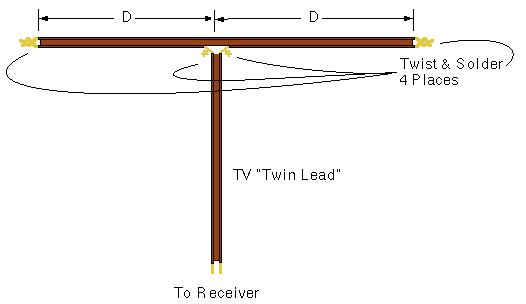


ASSGNMENT 2


WHAT IS THE IMPORTANCE OF THE SMITH CHART IN RF SYSTEM


The Smith Chart, invented by Phillip H. Smith (1905-1987),[1][2] is a graphical aid or nomogram designed for electrical and electronics engineers specializing in radio frequency (RF) engineering to assist in solving problems with transmission lines and matching circuits.[3] Use of the Smith Chart utility has grown steadily over the years and it is still widely used today, not only as a problem solving aid, but as a graphical demonstrator of how many RF parameters behave at one or more frequencies, an alternative to using tabular information. The Smith Chart can be used to represent many parameters including impedances, admittances, reflection coefficients, scattering parameters, noise figure circles, constant gain contours and regions for unconditional stability.The Smith Chart is most frequently used at or within the unity radius region. However, the remainder is still mathematically relevant, being used, for example, in oscillator design and stability analysis.....